Rover
Introduction & Inspiration
My first big project. I created this project the summer after my 1st year of community college. I created it at the time because I was really big into NASA and space after completing the NASA NCAS program during my spring semester. Essentially, NCAS is a program offered by NASA for community college students and it introduces them to the world of the space industry and NASA itself, the two main parts are online, but it really inspired me to work on space related stuff for my career. Being my first big project, I made a lot of mistakes, and honestly I never made it quite work right, regardless I learned so much from this project, and I'm grateful for attempting it with the skills I had at the time.
Mechanical Design
Inspired by NASA's Curiosity and Perseverance Rovers, this rover loosely tries to replicate them. It has 6 motors and 6 wheels, a camera, and a robotic arm (never quite worked). I designed this using Siemns NX which was cool because a lot of the aerospace industry uses this CAD software. The overall chassis design is quite simple though, but it was easy to assemble. Here is a screenshot of the completed 3D design:
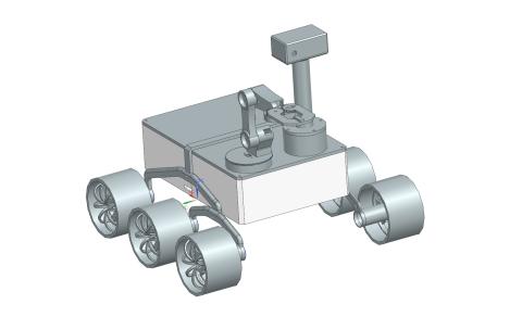
Some of the bigger issues I faced mecahnically was the design of the wheels. I wanted them to look just like the Mars Rover ones but it took some time to figure out how to get the curved rims of the wheel, but I managed to figure it out with time. I also spent some time on the robotic arm, I was using this project as a reference: Mini Robotic Arm with Arduino I believe the issues with the robotic arm not working is more of an electrical problem though. I'll explain more later.
Electronics
The electronics of this project center around two boards, a regular ESP32 and an ESP32-CAM. The ESP32-CAM is the main communication board it takes the web app comands, shows off the video feed and communicates to the controller board what motors and servos need to turn on. I made a perfboard version of this, then I created a PCB, here is the fully assembled PCB:
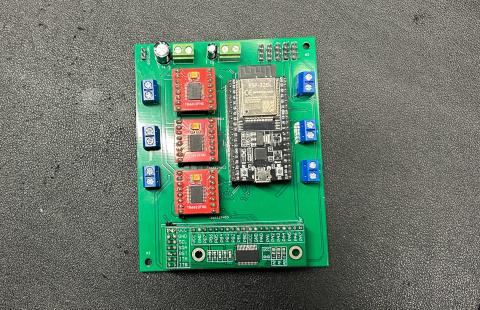
This is the list of the main electronic components for the project:
- MCU: ESP32 and ESP32-CAM
- Pin Expansion: MCP23017
- Motor Drivers: 3x TB6612FNG
- Motors: 6x JGA25-370
- Servos: 4x MS90S
- Battery: 11.1V 3S LiPo Battery
- Buck Convertor: XH-M401
While the PCB worked well, I should've added capacitors next to the power pins for the servos as I believe not having them caused the servos to brownout and not turn properly. I also could've used a PWM driver board like the PCA9685 to drive them as well. Speaking of power, outside of additional experience in designing PCBs, I also learned from this project basic power managment, which has been super useful for my future projects as well. This project made me understand how to properly step-down voltages, determine which components need adequate current and voltage, and overall safety practices when working with batteries.
Software
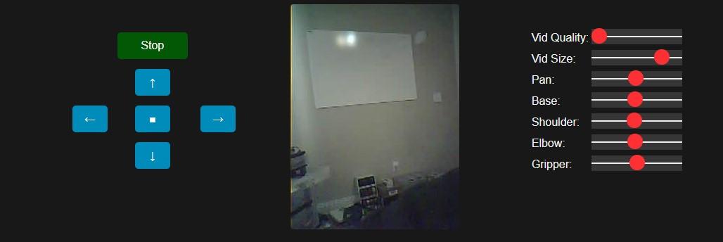
The web controller software is run on the ESP32-CAM, this code is a modified version of DroneBot Workshop's ESP32-CAM Robot Car. The main modifications is the additional communication code for the main controller board with the regular ESP32, and additional sliders for the individual servos. DroneBot Workshop's codebase was very useful, and helped make this project possible so big thank you to him. Here is a screenshot of the camera feed and controls:
Conclusions & Future Work
While this project wasn't completely successful, I still believe I learned the most about electronics and CAD design due to attempting a project like this on my own. I do want to make a completely working version of this someday, but the main aspect I would like to focus on first is definitely the robotic arm.